Monarch 10ee Lath Power Unit No Blue in the Tubes Problems
Instead going the VFD and AC motor route, I decided to try building a new DC motor controller. I wouldn't really recommend this approach, but there are some reasons that Monarch used a DC motor in these things. Two primary reasons are: DC motors can cover a wide RPM range, and DC motors have a lot of low speed torque. Drill/drivers of the cordless or even of the older corded era are a good example. Spin fairly fast, and under load the slow down but can develop a lot of torque to turn in a screw or turn a large drill bit. Starter motors on your car are also DC motors, again low end torque, but there your battery is also DC so that makes it an easy match.
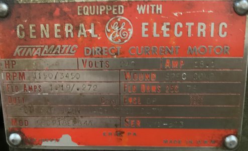
My 10EE came with a 5 HP DC motor. Here is a copy of the data plate,cropped a bit closer than the above picture:

Volts: 240,
Amps: 18.1
RPM: 1150/3450
Fld Amps 1.19/.272
SEP EXC 120V MACH TOOL DUTY
This means it wants 240VDC on the armature, at 18.1 Amps, to achieve 1150 RPM. At 1150 RPM, the field needs 1.19 amps at 120V. To achieve 3450RPM, we need to REDUCE the field current to 0.272 amps.
To get less than 1150RPM it'll need to be fed a voltage less than 240VDC on the armature.
So basically this thing needs two variable output DC power supplies. One for the field and one for the armature.
Converting AC to DC is why these things get complicated. Monarch went through a lot of variations in making this work. Some of the earliest 10EE's used an AC motor to turn a DC generator to run the DC motor. They went through a couple generations electronic approaches, mostly using old fashion vacuum tubes. I'm sure those of us over a certain age can remember when every hardware store had a tube tester and stocked a few vacuum tubes, but those have gone the way of 8-track tapes. Or is that cassette and VCR tapes?
240VDC is not straightforward to generate from your 240V single phase AC circuit. While theoretically 240VAC is actually the RMS (root mean square) voltage and the AC line sinusoid actually peaks out at 240 * sqrt(2), roughly 340 volts, RMS voltage is used so that RMS voltage * RMS amperage = average power. (AC current is also measured RMS). Volt meters and current meters are calibrated in RMS volts or amps. Anyway, converting AC to DC isn't perfect so typically you can't get 240VDC out of 240VAC for a high powered circuit. (Remember we need 18.1 amps). All we need is 20 car batteries in series, right?
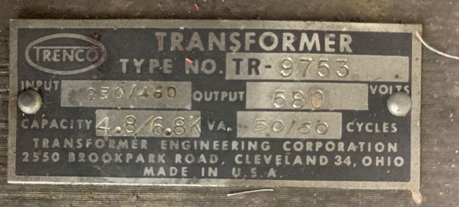
Why didn't they use a DC motor with a smaller voltage requirement? You can build a 5HP motor that uses less than 240V, but the trade off is the motor gets bigger. So obviously they were trying to keep the motor to a size to fit in the base. To get the enough DC voltage, the easiest solution was to use a transformer to raise the AC voltage up higher than 240V. (Transformers don't work for DC). Monarch used at huge 6.8KVA transformer to boost the AC voltage up to 580 volts AC (that is not a typo).

I'd guess that transformer weighs at least 100lbs. I have it on my bench. Unfortunately the leads on it are corroded beyond usable. So it makes a good doorstop I guess.
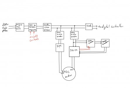
I did some reading and searching, and found a few people had successfully used Parker/Eurotherm DC controllers, namely a 514-32 and a 506 or 507 as the two DC power supply controllers for 10EEs using single phase 220V. Here is the basic power circuitry schematic I came up with for using those for the motor in my 10EE (note that there are several different DC motor options, 3HP DC was more common than 5HP).

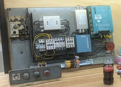
The "boost transformer" on the far right is the replacement for the above Monarch original. The Parker 514 is a solid state unit and a bit more efficient than the older tube electronics so I only need around 340VAC into the 514 to get full rated power out of the existing DC motor. Her's what that schematic looks like in implementation:

This is the panel that lives under the lathe bed behind a door on the front lower right of the lathe. The top left contraption is a 3 pole (3 phase) switch that protrudes through the door and has a large on/off handle. That switch is the only original equipment on that panel. The smaller panel in the lower left has the original on, off, and coolant switches. Note that the original panel had a nice easy to press protruding "On" switch, while the Off switch is recessed. Obviously modern safety standards have changed.
The blue boxes on the right side are the two Parker DC controllers, purchased used off of Ebay. The 514 was not cheap, $400+ used. (Did I mention that the VFD route made a lot of sense as long as the reduction gear was retained?) Obviously this panel doesn't include the DC motor itself, nor does it include the boost transformer. (Actually the motor can be spun up without the boost transformer, just doesn't deliver full power).
This doesn't cover a completely working setup yet. The 507 and 514 need some control inputs that tell it what voltage and current to deliver to the motor to give the desired RPM.
Source: https://www.hobby-machinist.com/threads/1964-10ee-lathe.91045/
0 Response to "Monarch 10ee Lath Power Unit No Blue in the Tubes Problems"
Post a Comment